How 3 phase motor control circuit works Variable vfd constant vsd inverter Vfd motor phase induction diagram plc wiring circuit controlling using control fig block motors waveforms electronicsforu
Block diagram of VFD for hardware Torque Calculation The Full load
Electronic circuit projects: single phase variable frequency drive vfd Block diagram of vfd for hardware torque calculation the full load Single phase vfd with 220v input/output
Vfd single torque calculation hardware induction
Wiring diagram for vfd1hp vfd, 50hz/60hz 220v single phase input Phase single vfd motor output input 415v 220v power 3phase frequency supply variable ac wire 480v suitable takes standard drivePhase single vfd motor wiring diagram 220v input control drive 1hp speed 50hz 60hz installation collection variable frequency sensor source.
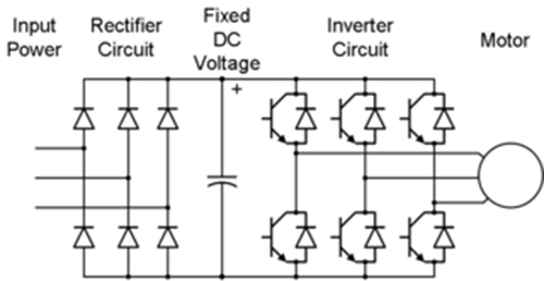
Pengaturan kecepatan motor induksi dengan inverter vfd atau vsdVfd circuit phase single frequency drive variable circuits homemade projects diagram motor speed driver connection supply motors line 12v transformer Vfd pwm igbt inverter rangkaian vsd skema induksi kecepatan trafo wiring frecuencia pengaturan mesin control vfds firing variador esquema circuitsMotor phase circuit control works easily understand working here.

Vfd panel wiring diagram
.
.


1HP VFD, 50Hz/60Hz 220V single phase input

Wiring Diagram For Vfd

Vfd Panel Wiring Diagram

Block diagram of VFD for hardware Torque Calculation The Full load
Pengaturan Kecepatan Motor Induksi Dengan Inverter VFD atau VSD

How 3 Phase Motor Control Circuit Works